transforming the transformer
In the last post, Design of an all-pass Hilbert Transformer filter, we began with the pole/zero pattern shown in Figure 1: |
| Figure 1 - Hilbert Configuration in the s-plane |
We then followed the process:
- Divided the filter into 2 halves called filter A and B
- Transformed into the z-plane
- Added a unit delay in series with filter A
Which gave us a Hilbert Transformer - a filter bank that takes an input and produces 2 related outputs with phase difference 90°. You should read that post to remind yourself how the filter was divided into two - by interleaved poles and zeros (and not by the 2 lines shown on the s-plane)
There is an additional step in the above sequence that we can perform:
- Transform in the s-plane
pole/zero translations
For example, figure 2 shows a shift or translation of -pi/2: |
| Figure 2 - shifting the Hilbert configuration by pi/2 |
This results in a 90° rotation in the z-plane compared with the Hilbert Transformer:
 |
Figure 3 - both (shifted) filters plotted in the z-plane (distant zeros at +/- 23.14i and +/- 4.81i omitted)
|
I have plotted both filters together but they should be considered as separate interleaved filters.
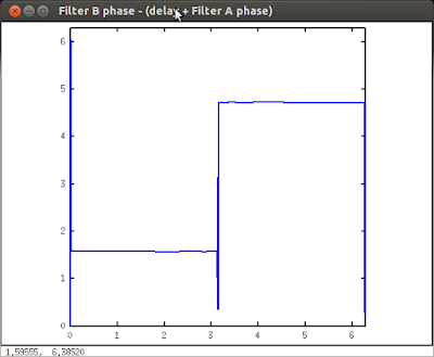
We can then follow steps 1,2 and 3 of the process to produce a pair of all-pass sections with the following phase response:
 |
| Figure 4 - phase difference between filter B and delayed filter A |
This new filter bank produces a pair of outputs 180° apart in the range 0 Hz to pi/2 Hz and 0° apart in the range pi/2 - pi Hz.
If you sum the outputs of the filter, the low frequencies (0 < f < pi/2) cancel out whilst the high frequencies (pi/2 < f < pi) reinforce each other. The result is a high-pass filter with a cut-off frequency at pi/2 Hz
On the other hand, if you take the difference of the filter outputs the frequencies combine in the inverse sense and you have a low-pass filter. So we get 2 filters for the price of 1 - a bargain.
[We can equally do the pole/zero translation directly in the z-plane just by rotating the Hilbert configuration through 90° to take it from the real axis to the imaginary axis.]
transforming the transformation
There are additional geometric manipulations we can perform in the s-plane (or indeed the z-plane) to alter the transition frequency of the phase response of figure 4.
pole/zero scaling
We can break the pi separation of the two s-plane rows by squeezing them together (or moving them apart).
 |
| Figure 5 - Hilbert shifted by pi/2 and squeezed by pi/2 |
This "pi/2 X pi/2" operation results in the z-plane distribution:
 |
| Figure 6 - the pair of interleaved (shifted and squeezed) filters mapped into the z-plane (distant zeros at 16.36 +- 16.36i omitted for clarity) |
Again, we follow steps 1,2 and 3 of the process to give the phase relationship:
 |
| Figure 7 - adjusted phase difference between filter B and delayed filter A |
This new relationship has produced another low/high pass filter pair with the transition frequency now at pi/4.
You can easily see that by applying different degrees of 'squeeze' or 'stretch' on the pair of s-plane lines we can change the transition frequency to whatever we like. The only caveat is that when the transition frequency moves close to 0 or pi, you have to reduce the order of the filter (i.e. use a lower 'n' in the filter generator function) due to the poles and zeros of the z-plane conjugate pairs interfering with one another.
RAW~


