 |
Figure 1 - poles and zeros arranged according to power-of-2 multiples of pi:
One row at jω= 0 and another identical arrangement at jω = pi.
|
It's hard to tell from the figure, but there are n=20 poles and 20 zeros at jω=0 at the points:
σ = +/- [pi, pi/2, pi/4, pi/8 ... pi/(2^20)]
(with the same again at jω=pi.)
Lets (not entirely arbitrarily) divide the filter into 2 parts given by alternate pole and zero positions across the σ-axis:
 |
| Figure 2 - filter B. Poles and zeros at positions given by pi*(2^-(2n)) |
 |
| Figure 3 - filter A. Poles and zeros at positions given by pi*(2^-(2n+1)) |
We can convert these analogue filters to digital ones by employing the matched z transform (see previous post): z <- exp(s) - i.e. we simply take the exponential of each pole and zero:
 |
| Figure 4 - Filter B transformed into the z-plane (zeros at +/- 23.14 not shown) |
 |
| Figure 5 - Filter A transformed into the z-plane (zeros at +/- 4.81 not shown) |
 |
| Figure 6 - Phase difference between filter B and filter A |
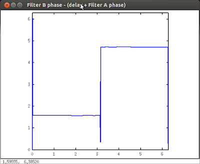
It would be nice if we were able to flatten out those phase slopes to produce some manner of constant phase difference. It turns out that you can achieve this by adding a delay in series with one of the filters, as demonstrated in figure 7.
 |
| Figure 7 - Phase difference between filter B and delayed filter A |
The preceding analysis implies that if we were to create a parallel filter bank with filter B in one path and Filter A in series with a unit delay (z-1) in the other, we would have a means to produce a constant phase difference of pi/2 over a wide band of frequencies between 0 and pi (Nyquist).
There are actually theoretical limits at exactly 0 and pi/2 but the more pole/zero pairs (produced by higher 'n' in the filter generator equation, exp(pi/2^n)), the wider the effective band. Unfortunately the process has a diminishing return which comes at the cost of filter settle time - since poles positioned ever closer to the unit circle result in filter 'ringing'.
The order n=20 example under discussion has an effective bandwidth all the way from 1 Hz to 22049 Hz at sampling rate 44100 Hz (i.e. with Nyquist frequency = 22050 Hz).
This type of filter is known, by employing a touch of artistic licence, as a Hilbert Transformer. Although (unlike a true Hilbert Transformer) it alters the phase of the input reference frequency, it does produce an analytic signal - a 'real' and 'imaginary' pair which are pi/2 degrees out-of-phase.
RAW~
No comments:
Post a Comment